Heya,
I had a broken Philips DVD player lying around for sometime, so I decided I’ll take out the LCD panel inside it and play a little.
First of all, I discovered that it was a VFD not a LCD, but programmatically that wasn’t a huge difference !.
The unit contained 7 digits, each digit was a 16 segment VFD, And was driven by an ET16312n chip !
First thing was to get the datasheet to know how to wire the panel to my computer, and how to talk to it !
After some research I found the NEC datasheet and learned that most VFDs have the same NEC standard and if you manage to program one panel, it’s most likely that any other brand will work the same way with minor mods in your code !
After some tracing I managed to get the serial leads, which were STB, CLK, Din, Dout (Din and Dout are shorted on my board, input is read on the rise of CLK, and outputs are read on the fall of CLK)
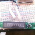
After wiring those pins to my parallel port (Yeah I didn’t have a serial interface and I’m too lazy to buy one, and I’m bad with soldering too !),
I connected the STB pin to pin 2, Din/Dout to pin 3 and the STB to pin 4 on my parallel port.

Power connections are give in the datasheet pins 7, 14, 27 are for Vss, Vdd, Vee respectively (You’ll need to power sources for that, Vss it in the 5.5 v Range, and Vee goes down to -30 volts (That’s a VFD thing, don’t ask)
After all the wiring and powering is done, it’s time to go to my PC and start writing a driver code !
My box runs Ubuntu, you’ll just need the `build-essential` package for this. You probably have it, if not just “sudo apt-get install build-essential”
You can go ahead and download the code attached to this post, it’s written in C, just compile and connect your panel and things should work right away 🙂
I’ve written the code to read text from a file, then scroll it on the screen (since we can only have 6 chars displayed at a time)
Another issue that came across me was how the encoding of the characters worked, I tried lots of methods but the easiest (for me) was to calculate it by pen and paper, took around 20 minutes to calculate the binary representation from letters from A to Z. they are defined in the 16seg.h header file for your convenience 🙂
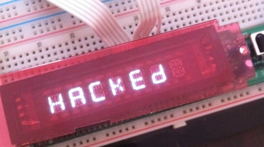
Here’s a picture of the final product, hope you like it:

For the time being that’s all I reached and all I’m going to do on this project, it can be pushed further but for my concerns, it was just for fun and I don’t really need it. however there are many cool uses that can be done (since it contains push buttons and an IR sensor), think about the possibilities, perhaps yet another twitter notifier that works via a TV remote ?? 😉
If you have questions leave it in the comments or email me, I’d be happy to help anytime !
Happy reversing 🙂
Downloads:
vfd.tar (Source code)
UPD16312 (Datasheet)


Pingback: VFD Hacking - Hack a Day
Pingback: VFD Hacking | You've been blogged!
Pingback: .:: Arindam's Blog ::. » Blog Archive » VFD Hacking » .:: Arindam's Blog ::.
Nice work….
As far as what to do with it, put your current CPU load etc out to it….
Thanks QBert, Yeah I tried putting CPU load on it, was fun for a while, but I didn’t like the looks, it’s on a breadboard with a huge panel with buttons, etc…
If i wasn’t so lazy, I probably would write the driver for the buttons and IR too, and embed it into my case, that would be more fun. but as I said, I’m so lazy 😉
Hi. nice job. I found I have a VFD on an almost identical looking board, also using the UPD16312 chip. I’m going to drive it from an arduino, that’s easy enough, but finding a solution for the large negative voltage is giving me a headache. How did you do it?
Hey Coda, Yeah i’m sure the Arduino will drive it perfectly, i know how annoying it is to get all that negative voltage, here’s what i did:
Connected two Generic DC adaptors to a common positive, and set one to run on a +5v, and the other to run on -12v
the common positive node will be the Ground, and you’ll have a +5 and -12 to run your arduino and vfd
if you need a schematic let me know I can sketch up something quickly for you, keep me updated about your project 🙂
Hi i was just wondering if you could post a schematic please also could you show me a better picture of the wires on the breadboard i’m having a bit of trouble finding the serial wires. Please 🙂
Hi jack, sure i’ll try uploading a schematic later tomorrow, i’ll also email it to you and update the post here 🙂
Thnx a lot Qbert! I’ve got the same DVD player, and i just need vfd display. I lost so much time to find any manual for ET16312N (driver) until found Your blog. So again – THANKS A LOT Qbert!
Hi QBert
Nice work!
Just came across the same display.
Could you please confirm that we need to provide -30V power to lit the display ?
Any idea of the required current ?
I was thinking about using basic volatge multiplier using diod/capacitor cascade.
Hi Barbudor !, yeah I’m sure it’s -30v , but anything in the -20v range will work, how are you planning to power it? think the current from a normal 12v adaptor will work !
Hi Berg
Don’t know yet. Would have a 5V PSU, then as Isaid, may be doing a basic charge pump
Using pulsing digital pin and a multiplier like http://en.wikipedia.org/wiki/Voltage_multiplier, it’s easy to get a few -tenth of volts but not much current.
Do you have any idea of how much current is required on the -20..30V ?
Hey Mostafaberg, I have an arduino and the same vfd.
I would like know if it’s possible to run this vfd if the arduino run on usb?
thanks
Hi, Mostafaberg!
I made this project, but the chip STM8L inside.
Change your prog for my chip, but it wasn’t working.
I found two mistakes in your source code.
Now it’s good working .
Thanks for your idea an good luck!
Photo:
http://forumimage.ru/uploads/20140921/141131073671815131.jpg
Video:
http://www.youtube.com/watch?v=w_I80QWXSZs
And source code for STM8L152k6 chip:
http://rghost.ru/58132823
Amazing Job !, this looks even more functional than what I did, what are your plans for it ?
Hi Roman
I’m new to electronics.I just found an old display (from an old philips dvd).
Can you tell me what exactly is that you used to make the VFD work and show words.
Sorry if it’s too basic for you but i really want to personalize one old vfd
thanks
i cant open code in my windows..
please provide (.ino) file of code
BY THE WAY great job…..
stay SAFE.
hi @garv, sorry for the late response, didn’t see your comment until now, there’s no info file , you need a C compiler, that’s all 🙂 please remember this is ancient code from an old project, I would recommend going with a modern solution 🙂
Hello, i have problem with . Constantly underlines in red in the Arduino IDE. How i cam fixed this?
with
You can’t use this code in the Arduino IDE 🙂 this C code actually communicates with the VFD via parallel port 😀 so there’s no arduino involved
with “”
Greetings Berg.
I have a Samsung VFD with 7 Digits and 13 Segments similar to yours and, based on another sketch, I’m trying to make a Clock, but I have a crucial question regarding the characters, for example, here:
unsigned int segments [] = {
0b01110111, // 0
0b00100100, // 1
So, as you can see in the image I am sending you (https://www.4shared.com/photo/S2tJOLvZea/Tabela_de_Grades_e_Anodos_do_D.html), how can I define the 13 characters of my VFD in the unsigned above that has 8 characters? I do not understand! Could you explain it to me?If you prefer, you can reply in my email. Thanks
Hi Daniel, i’m not sure i’m following what you mean, but if you see the segments it’s actually an array, you can define a new entry for each charcter you want in the segments arrray, to know which binary values you can simply toggle each 1 and 0 to see which segment it lights up, then combine the ones you want to make the character you need.
Can’t open the link et seems to be broken 🙁
Hello Berg! Again I have another question:
Where is the sketch for Arduino, because I have a board with a VFD with 7 Digits and 13 Segments that uses the PT6312 chip and should work with Arduino. In fact, I would like to make a Clock; Thanks
Hi again Daniel, sorry but this isn’t arduino based so there’s no sketches, if you need any assistance just email me as i don’t check the commetns often!